
The Fantastic Vent developed two issues really quickly. It surprising since these units have a great reputation. The first issue is a dry bearing type chirp developed in the motor unit. The second issue is the cover rattles while traveling over 60 mph. These units are rated for 85+.
The Fantastic Vent manufacturer send a new fan blower unit to fix the dry bearing chirp and a new lift arm and cover to fix the rattling cover issue.
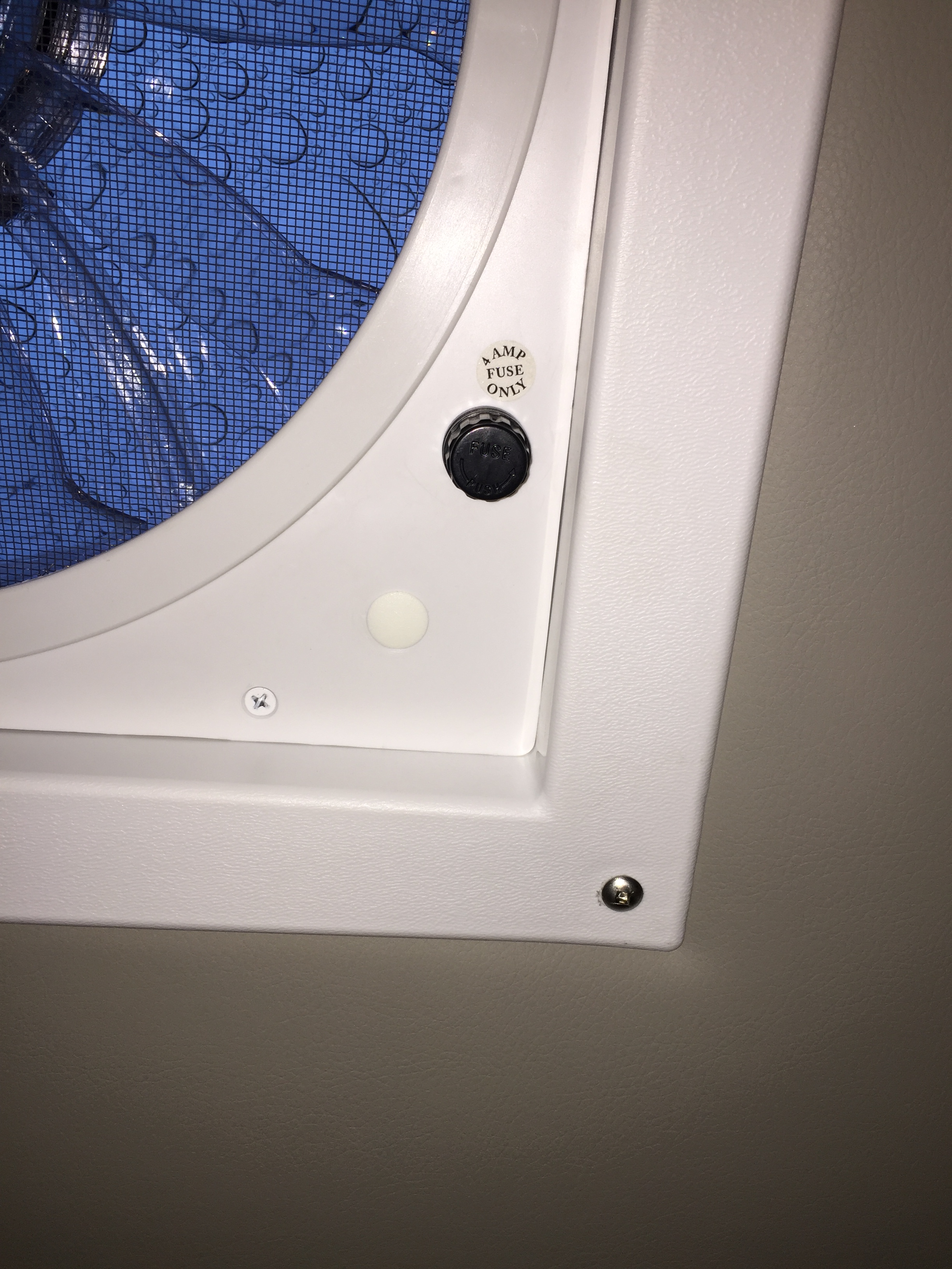
The first task is to remove the fan fuse to cut power to the unit. It is a inside a little black cap located on the face of the fan unit. Twist unlatch the cap and remove cap and fuse. While there remove the screen. There is a little spot where the screen edge has an opening to get your finger under. Carefully pull the screen straight down. It is a little stubborn the first time you do it.
Get a ladder and climb up to reach the cover on the roof of the RV. I have a Xtend+Climb ladder that worked well.
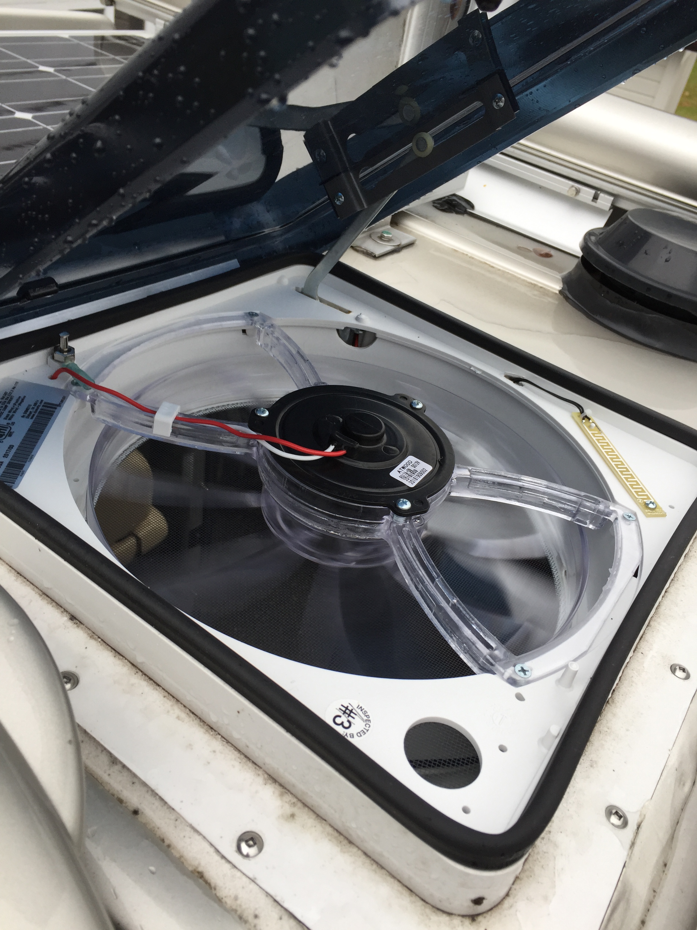
The wires are held to the fan motor frame with a small clip. It is the white part holding the wires down in the photo below.
Double check that the fuse is pulled for the fan. The main circuit breaker could have also been shut off.
Remove the clip and cut the wires.

Remove the Fantastic Vent cover by removing four screws that attach the cover hinge to the frame of the Fantastic Vent.

With the cover removed there is easy access to remove the four screws attaching the fan motor unit to the frame. The photo below is out of order. I is of the new fan motor unit being installed. You may notice that the electrical lines are not yet installed. The originals are removed.

Preparing the new fan motor unit.
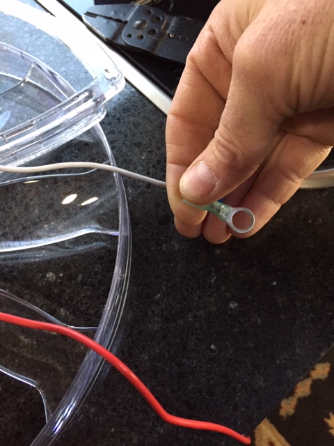
The replacement unit came with attached crimp connectors. It is intended to cut the original wires and splice in the new fan motor unit using the crip connectors provided. This would be easy and quick however I chose to remove the crimp connectors and add new connectors matching the original installation. Below I am removing the crimp connectors.

You can attach the white (ground) ring terminal at this point. This is a 5/16″ ID Ring terminal. After crimping give it a slight tug after to verify a solid crimp (not too hard or you will end up pulling it off. An afterthought I could have put shrink tube on this connection to make it more robust.
The terminal for the red (hot) wire is installed after the fan motor unit is installed. There is a little hole in the frame the wire gets threaded through before the terminal can be attached. Below is a photo of the terminal attached to the red wire. Reminder, this gets crimped on after the fan motor assembly is installed and the wire threaded through the small hole in the fantastic vent frame.

Here is a photo of the ground (white wire) attached and the red hot wire threaded through the small hole. To finish the wire get pressed into a groove in the support arm of the fan motor assembly and a wire clip keeps it there.
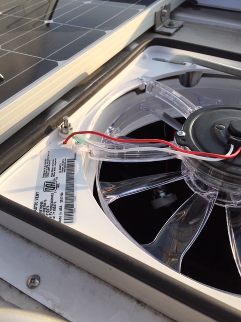
Replace the wire clip and the hood. The finished job looks like this.
Restore power to the fan unit by replacing the fuse and if the circuit breaker was turned off turn it on. Test the unit.

Leave a comment